Subject Medical waste incinerator Day Capacity 1000kg Waste Type Medical waste https://www.hiclover.com/#!/Model-TS100-Medical-Waste-Incinerator-100-150kgs-per-hour-capacity/p/416001748/category=0 Description Brand Model Fuel Type Medical…

Types of Incineration That Are Used in Hospital
Phone: +86-13813931455(whatsapp/wechat)Website: http://www.hiclover.com/ Email: [email protected]: [email protected] Nanjing Clover Medical Technology Co.,Ltd. Model YD-100 Picture Burning Rate 100-150 kgs/hour Primary Combustion Chamber 2000 Liters Secondary Combustion Chamber 500…

400mm Melt blown Production Line and 1600mm Melt blown Production Line and ES Fiber Production Line and and N95 Mask Machine and Disposable Mask Machine
1. N95 and Disposable Mask Machine 2. 400mm and 1600mm Melt blown Production Line 3. ES Fiber Production Line…

N95 Face Mask Machine Production Line on Sale Now! $250,000USD per set
N95 Face Mask Machine Production Line on Sale Now! $250,000USD per set N95 Face Mask Machine Production Line on Sale…

3layer Facial mask machine
Zhangjiagang Tengxiang Machinery Co., Ltd. Mobile: 0086-13962221749(whatsapp) Wechat: chncheumg Email: [email protected] Face Mask Machine for Coronavirus Disease COVID-19 平面口罩机参数: Semi-Automatic Mask Machine…

Incinerator Light Shipping Weight Small-Scale Hospital Medical, Containerized Mobile Incinerator Optional
Light Weight Small-Scale Medical, Mobile Optional Type Model YD-30 Picture Burning Rate average 30 kgs/hour Feed Capacity average 40…

Equipment Specification for Children & Maternity Hospital Charsadda
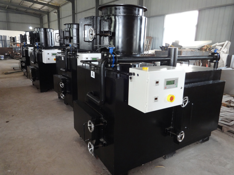
Designed to burn disposables that can and should be destroyed on-site. Theses wastes include infectious and contaminated “red bag.” Surgical dressings, plastic test devices and other wastesFast, complete, efficient waste disposalDual chamber combustion, Chambers insulated and lined with high temperature refractory. Programmable digital temperature controls, temperature indicators and charge recorder. Modulating control for fuel and air lowers fuel consumption. Minimum installation and start up timeAluminized steel jacket lined with refractory and firebrick. Monitors recorders and other accessory equipment should be available. Charging system:• Vertical charge door on primary chamber.• Pneumatic or hydraulic ram charging system. • Auto shut down of the door after charging.• Primary and secondary chamber temperature displayed and recorded (optional)Charging rate:• Up to 100kgs per hour of waste or red bag waste rated at 2200 BTU’s per kg.Fuel:- Natural GasCapacity (Cubic Mtr): 1.65M3 or moreAve Capacity: 100kg per hourSecondary Chamber Capacity (CubicMtr) :3.88 or moreLength (mm): 1880 or betterWidth (mm): 1280 or betterHeight Incl. Flue (mm): 7700 or betterAsh Door Opening (mm): 475×900 or betterMin. Operating temperature: 90 degree centigradeMax, Operating Temperature: 1350 degree centigradeResidency time in Second Chamber: 2 secTemperature Monitoring: Both for primary and secondary chambers.Loading SystemManual/semi-automaticWaste destruction efficiency:> 90% by weight Filter: Ceramic or other equivalent filters in order to reduce the induction of hazardous air pollutants, particulates, co,dioxin/furane into the atmosphere.De ashing system: Manual/semi-automatic.The System must be quoted complete with:-• Plumbing• Electrical panels• Civil works•…
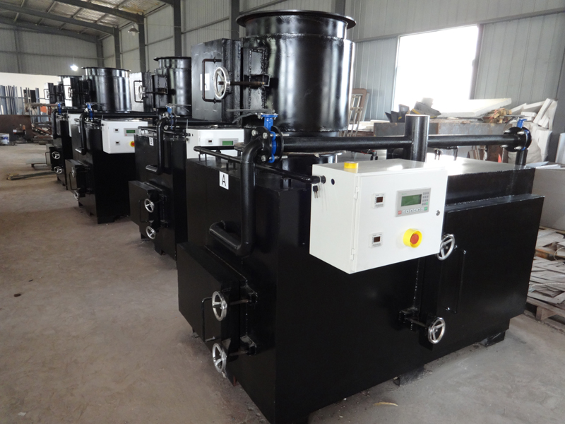
Secondary Combustion Chamber (After burner)
The plant must have four distinct sections that demonstrate three principles of turbulence, residence time and temperature retention. The regulated sections may include but not limited to: 1. Overall plant layout 2. Feed chamber/charging 3. Primary combustion chamber 4. Particulate scrubbers 5. Acid gas scrubbers. 6. The stack/chimney. 7. Minimum capacity of primary chamber = 0.18 cubic metres 8. Burn rate (rate of waste incineration) = a least 20 kg per hour 9. Should have a full width counterbalance loading door allowing easy access to the main chamber for loading and removing ash. Supply, Installation and Commissioning of An Incinerator in Eastern Hydros [ Page 28 2.2 Feeding and Charging Controlled hygienic mechanical feeding that does not negatively influence the air temperature in the primary and secondary chambers of the incinerator shall be used. 2.3 Primary Combustion Chamber. a) This chamber should be equipped with burners that use low sulphur fuel. b) The chamber should ensure a minimum exit temperature of 850 degrees centigrade. 2.4 Secondary Combustion Chamber (After burner) a) Should be fitted with burners that use low sulphur fuel. b) Ensure secondary air supply is controlled. c) Ensure residence time is not less than two seconds. d) Ensure that the gas temperature as measured against the inside wall in the secondary chamber and not in the flame zone is not less than 1100 degrees centigrade. e) Ensure the emitted oxygen content of the emitted gases is not less than 11% f) Ensure both primary and secondary combustion temperatures are maintained until all waste is completely combusted.
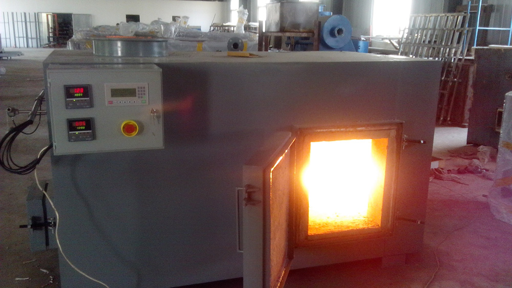
Incinerator Burn Rate 65kg/h minimum
Incinerator Burn Rate 65kg/h minimumWeight (kg), please indicate:Secondary ChamberGas Retention Time – 2 SecondsFuel – Diesel/LPG/LNG, please indicatePower Supply for Control Box – 220V-240V 50Hz single phaseMinimum operating temperature 850 °C, please indicateOne year Spare Parts Package for complete maintainability10m Hose Pipe, indicate lengthI000 Litre Fuel Tank + Pipe System, indicate volumeBurn Rate 150kg/h minimumWeight (kg), please indicate:Secondary Chamber Gas Retention Time – 2 SecondsDiesel/LPG/LNG, please indicatePower Supply for Control Box- 220V-240V 50Hz single phaseMinimum operating temperature 920 °C, please indicateOne year Spare Parts Package for complete maintainability10m Hose Pipe, indicate lengthBurn Rate 250kg/h minimumWeight (kg) please indicate:Secondary ChamberGas Retention Time 2 SecondsFuel Diesel/LPG/LNG, please indicatePower Supply for Control Box 220V-240V 50Hz single phaseMinimum operating temperature 920 °C, please indicate One year Spare Parts Package for complete maintainabilityBurn Rate – 150kg/hour minimumWeight (kg), please indicate:Secondary ChamberGas Retention Time 2 SecondsFuel Diesel/LPG/LNG, please indicatePower Supply for Control Box 220V-240V, single phase 50-60HzMinimum operating temperature 1200°C, please indicateOne year Spare Parts Package for complete maintainability

BRULEUR DE LA CHAMBRE DE POST COMBUSTION
Sont prévus 2 brûleurs du type à l’air soufflé au gasoil équipés des dispositifs de sécurité.A la mise en route du four les deux brûleurs sont allumés pour assurer la température minimale d’au moins 1100°C ; ils restent en marche successivement pour maintenir la température constante.Puissance thermique installée (290 + 350) KW.• Installing a readymade concrete base (Precast) with Height 30 cm above the ground and 20 cm below the surface of the earth. • The dimensions of the base are increased by (2 meters) from the edge of incinerators • The rest of the accessories in all the trends even allows the worker directly feeding and maintenance work, cleaning and move easily taking into account the tendencies of the base toward the door for drainage of water.• The floor coating must be high-quality epoxy paint.• Install anti-rust and heat Umbrella of brick and steel (pyramid shape) of (5) meters height above the ground which installed with the edge of the concrete base by thick galvanized columns • This umbrella Cover the site furnace and allow bringing the chimney8. CHEMINEE D’EVACUATION Constitué par un conduit métallique vertical de 8 m de long installée au-dessus de la chambre de PC, diamètre 630 mm en tôle d’acier au carbone avec garnissage intérieur en réfractaire 9. ARMOIRE ELECTRIQUE DE COMMANDE ET REGULATIONComposée de :Circuit 380 V- 50 HZ-3 phasesVoyant sous tensionCommande d’arrêt généralVoyant état des bruleursAffichage des températures des deux chambresMinuterie des temps des cycles.Une variation des vitesses des ventilateurs Le tableau et les câblages sont prévus aux règles CEI avec protection IP 55Microprocesseur pour le contrôle et la régulation des températures, ainsi que les cycles d’opérationCâblages réalisés selon les règles CEI. 10. INSTRUMENTATION DE CONTROLE ET DE MESURAGE CONTINU Les dispositifs suivants sont prévus : 1)Thermocouples pour la mesure de la température en chambre de combustion et postcombustion, à la sortie de l’échangeur dans la section d’entrée du filtre 2)Système de mesure de la concentration d’oxygène dans les fumées humides a la sortie de la chambre de postcombustion constitué de :Sonde de mesure de l’oxygène à l’oxyde de zirconiumPompe à la membranedébitmètre
